Dan Boccia (Alaska) provided the following article which provides a great starting point for wiring up your boat, what order you should follow, and some great words of wisdom that'll save you some heartache! I've inserted some notes and references where you see [EDIT] preceding some information.
[CAVEAT] Learn basic Ohm's Law and electrical design, how to use a basic multimeter, and the basics of working with electrical wire (types, gauges, crimping and attaching connectors - including on those big battery cables, etc). Reference to Nigel Calder's book is given below.
From Dan:
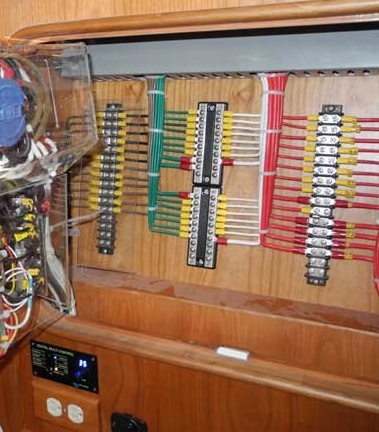
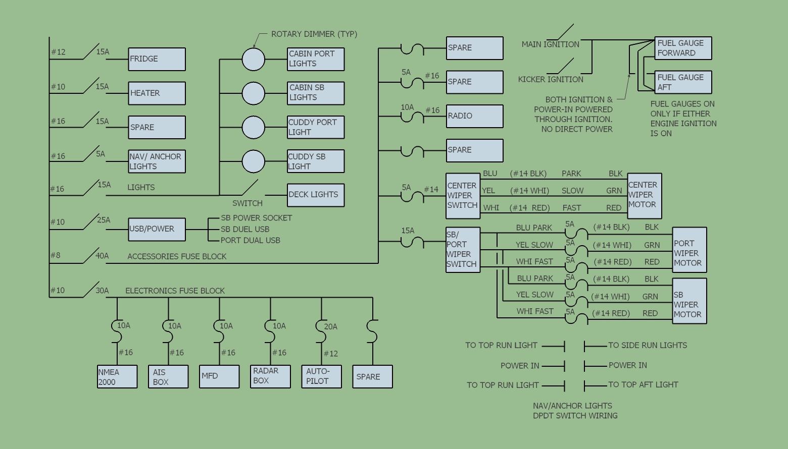
Finished the cabin electrical wiring finally. Deleted the cabin wiring diagrams above, replacing them with the diagram below, that now includes wiring for running/anchor lights through a double-pole double-throw (DPDT) switch. Also deleted a photo that came in sideways. I'll take some pictures of the finished installation in the next few days.
Here are my thoughts on the electrical system from what I have, in some cases painfully, learned:
1. Every single current-carrying wire should have circuit protection, period. Battery-mounted fuses make this easy to do these days, ABYC exceptions for main battery cables be damned. Be sure the circuit protection is appropriate for the smallest wire in that circuit. Know how to use ampacity and voltage loss tables when sizing wires, and be conservative (size wires up when in doubt).
2. Do your wire and equipment layout/design first before running out to buy equipment, wire, etc. Understand how things are going to be wired. There's a lot of time to be saved, and safety to be gained, by doing your layout ahead of time. I posted my diagrams for a starting point/inspiration.
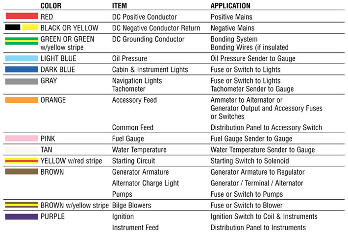
[EDIT] Make sure you follow ABYC Marine Wiring color coding on both your wiring diagram and in the boat. If or when this is not possible, use clear labeling on each end of every wire segment so that anyone doing maintenance in the future doesn't have to guess on the origin or application of any particular wiring. Color code table below.
3. Understand batteries - the different types, how to size them, how they like to be charged. Read Nigel Calder's book and understand it. Another huge time saver. Note that AGM batteries being charged directly from an outboard is not ideal and will likely result in reduced battery life.
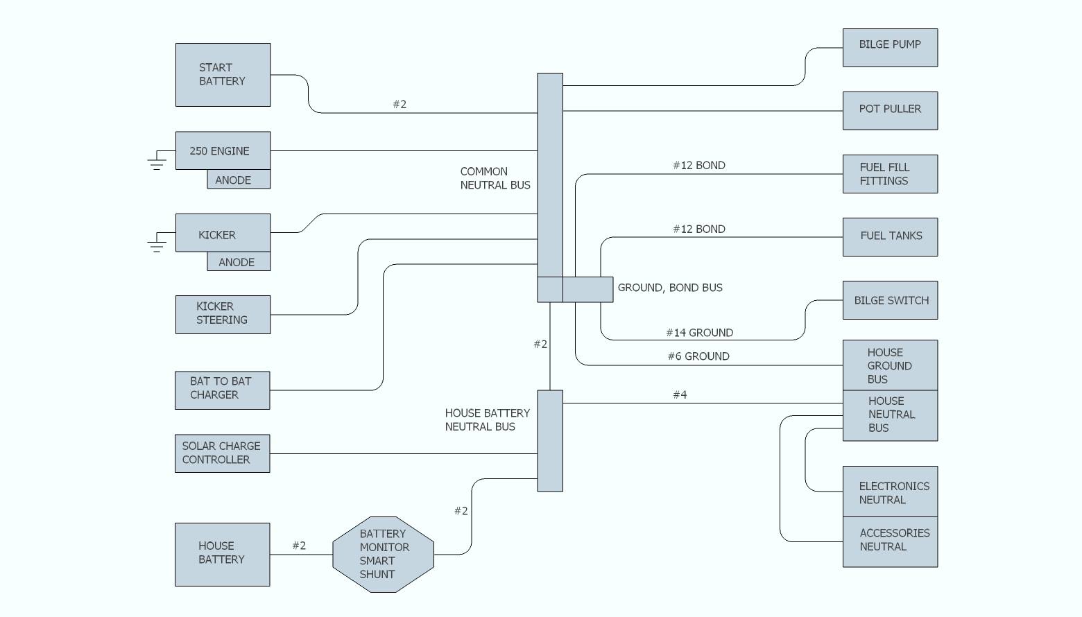
4. Be sure to bond any aluminum fuel tanks and tank fill fittings to your common neutral bus.
[EDIT] Bonding is not grounding, although it sorta is. "Bonding" means "In a direct current (DC) system, make all negative (0 volt) wiring the same voltage - no fractions of a volt above or below each other because that can result in 'ground loops' - unexpected current, corrosion, and shock potential". In short, bonding means all negative wiring must end up at a common 0-volt reference somewhere. Bonding includes ground buses, and those ground buses are connected to motors (your true source of 0 volts), and you motors should have zincs on them. The motor bonding connection must be to the same metal that eventually leads to the zincs - most modern motors have a bolt on them for this purpose).
5. Windshield wiper installation is a complex and shockingly expensive sub-project. I highly recommend the Roca W12 wiper motors over any of the junk from AFI, Marinco, etc. The Roca motors are quiet, and feature super nice infinitely adjustable sweep that is simple to set up, maximizing the sweep area on your window. I tried to avoid the synchronized controls in favor of the Cole-Hersey knob-type controls, but regret this. Get the synchronized controller with its switch, which I may ultimately end up doing. Having 3 wipers out of sync can drive you bonkers, and my attempt to get the outside wipers in sync manually failed - now the outside wipers really only function on interval, which should get me by for awhile. Get the control!
6. For most common anchor/all around top lights and side running lights, you'll need a DPDT switch that allows the forward-facing top light to turn on when you want running lights OR you want anchor light.
7. In general, the best sequence of work is to mount ALL of your electrical equipment, roughly run ALL of your wires a little long (all of them labeled at both ends), locate wire anchors (typically zip ties with anchor-blocks) then either start terminations on the field wiring and work toward the central panel, or vise-versa.
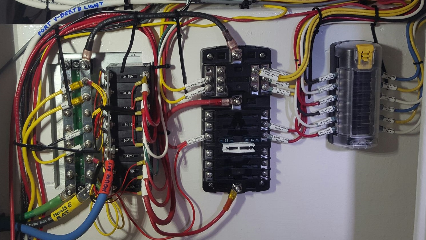
8. Have a way to label the wires worked out. I ended up with the Brady labeling machine that prints on heat shrink and love that solution. You can also use a cheap $25 label maker and use non-adhesive low-temp clear heat shrink to cover the labels. I could not find the appropriate clear heat shrink locally.
That's enough for now.
Moving on to the electronics installation now.....more opportunities to drill holes in the boat!
[EDIT] Some additional notes:
- Electrical wiring always needs service at some point - the ends corrode and stuff ages. You want to have excess wire near each end of a wire.
Electricians call this a "service loop" - there is enough extra wire at the ends for you to snip some off, add a new connector, and to reinstall. See next topic - drip loops - In a boat wiring job, you want to have 'drip loops' near each connection. A drip loop is excess wire that makes a downward U-turn from it's connector so that moisture or water will run (gravity) down to the U-turn rather than into a bus or connector where it can cause corrosion. See 'wrong way' and 'right way' drip loop photos below. The 'right way' is Dan's boat. The 'wrong way', surprisingly, came from a so-called professionally written article on boat wiring. In addition to having the drip loop, make sure that (whenever you can), the connectors are installed at an upward angle rather than straight out, so that water (again) will tend to run away from the connection, not towards. Finally, note that many marine connectors are available with silicone or other anti-water goop or coatings inside the crimp connectors to provide further protection.
- Ignition-proof electronics, switches, etc are preferred. Your fuel system, heating system, or anything that may unintentionally provide flammable liquid or gas to hidden areas can result in a boat fire. Ignition-proof (Blue Sea etc) components are designed to a) provide NO sparks, and b) are generally sealed so that if a spark IS generated, it's encapsulated in the device.
- Nigel Calder's excellent book: Boatowner's Mechanical and Electrical Manual
- Also recommended, Metal Corrosion in Boats by Nigel Warren. This book will also help with the understanding of bonding and corrosion in boats - a good read and an education for all boat owners.
- Purpose of BRANCH protection: Branch circuit protection is FIRE protection and it's ONLY purpose is to prevent too much current in a wire so that the insulation will not heat up to the point that it catches on fire. Branch circuit protection is NOT device protection!
- Purpose of DEVICE protection: Device protection is NOT for the prevention of fire. Device protection is in ADDITION TO branch circuit protection. It's purpose is to protect the devices in the boat, e.g. your electronics and other components - even motors etc. The best way to design is to design a POWER DISTRIBUTION system with complete BRANCH protection first, then for sensitive devices, provide ADDITIONAL inline protection - Example) You might have 16 amp DC power wired throughout the boat, branch circuits come off of that at DC buses, and each branch circuit provides power to a device. You would use wiring capable of more than 16 amps for the main power distribution and this wire should have a fuse or circuit breaker sized to protect THAT WIRE from over current. Each branch circuit would have it's own fuse or circuit breaker to protect the branch circuit wire (for fire protection) that is sized according to the gauge of the branch circuit wire. Finally, if the device is sensitive, you will also provide a device protection fuse or circuit breaker just for that's device's limitations (mfg info). An example might be a 4-amp branch circuit with a 4-amp circuit breaker that feeds a radio with a 2-amp maximum current ... you'd put a 2-amp fuse inline on the branch circuit wire (after the circuit breaker, before the radio).
- You can do this! Take your time and draw it up in advance, including routing through the boat, and work through it systematically - and read Dan's info above, the Nigel books, and all documentation from the manufacturers of everything you bought for your wiring (or is powered by your wiring).
Dan's cabin electrical diagram (general diagrams below):
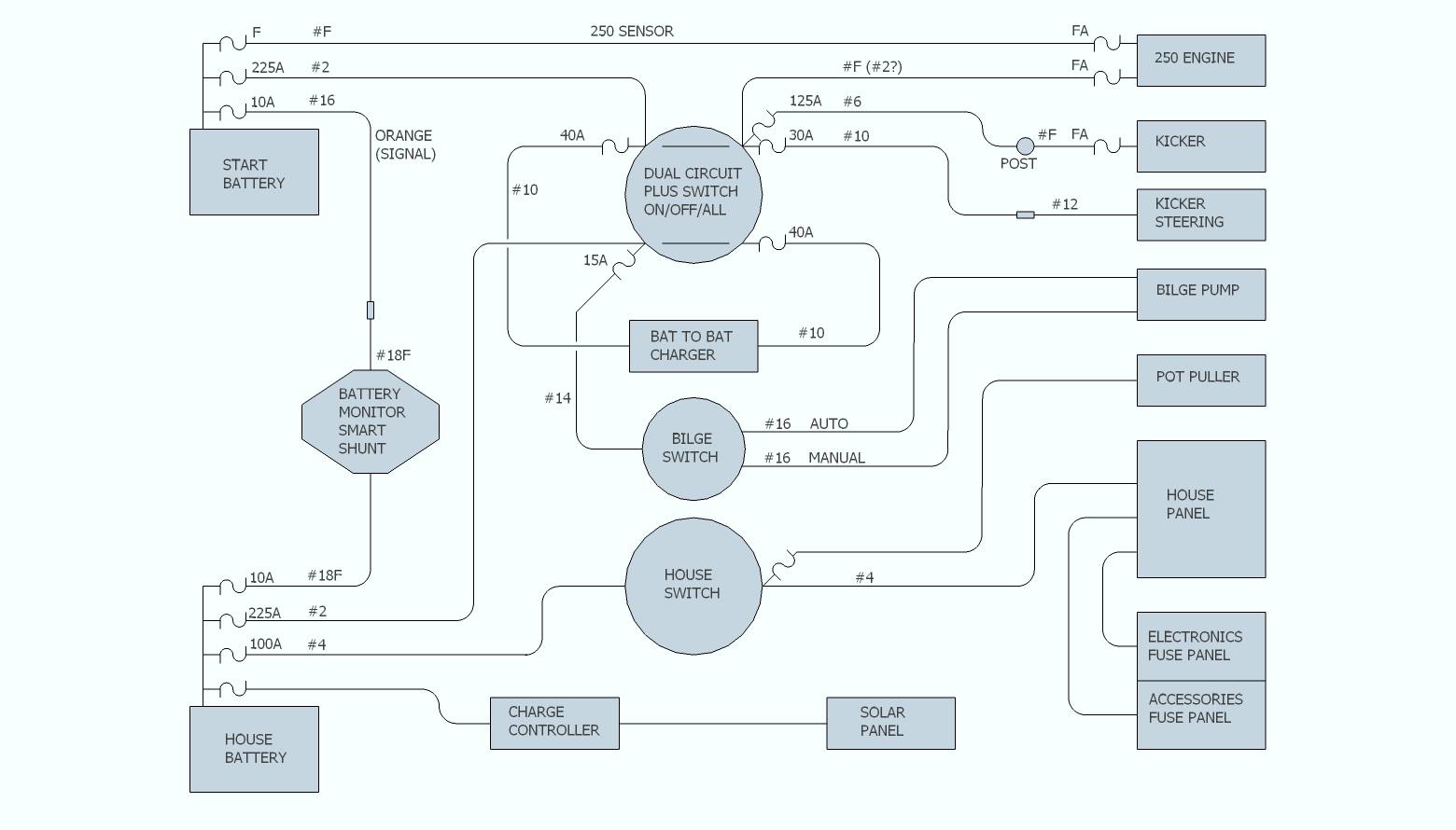
Dan's Power Distribution & Charging:
Dan's Neutral & Bonding:
ABYC Marine wiring color codes:
RIGHT way to use excess wire ('service loops') and drip loops, downward angled connections and awesome labeling!:
WRONG way to wire ... Looks GREAT, but there is ZERO slack for doing repairs and NOTHING to prevent moisture from running right into the connectors!